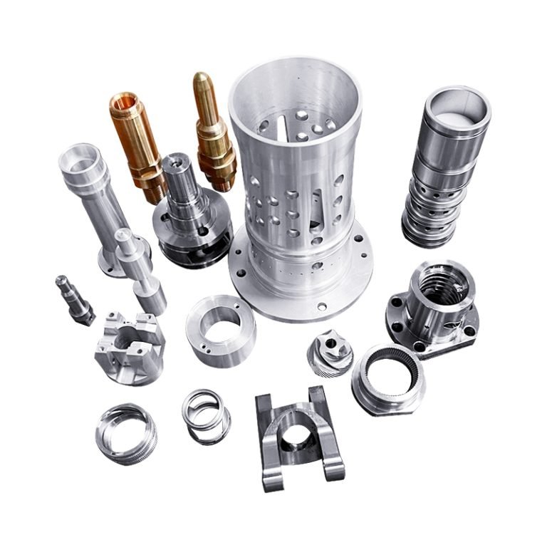
What is a Coupling?
A mechanical device used to connect two shafts and transmit rotary motion and torque. The coupling is usually designed to be flexible, it does not disengage under normal operating conditions and can be adapted to different types of shafts and application scenarios.
It transmits power between the shafts while allowing for some slight axial, radial or angular misalignment, which reduces the negative effects caused by alignment errors, different shaft speeds or different axial movements of the shafts.
Main Functions of Couplings
1. Transmission of torque: One of the basic functions of a coupling is to transmit torque on a rotating shaft. When a torque is applied to one shaft, the coupling, by its design, transmits the torque to the other shaft.
2. Connecting shafts: Couplings are used to connect two shafts so that they can rotate together. This is important for connecting different parts of equipment, mechanical components or drive trains.
3. Absorbing vibrations: Couplings such as flexible couplings absorb vibrations and shocks on the shaft. This helps to minimize the transmission of vibrations due to misalignment, non-parallelism or other irregular movements of the shaft.
4. Allowable shaft misalignment: Couplings are usually designed to be flexible enough to tolerate slight misalignment between shafts. This helps to avoid problems caused by installation errors or operating conditions.
5. Protecting equipment: Couplings act as a protective device in mechanical systems. In the event of abnormal loads or excessive torque on the system, the coupling can break or slide to prevent more serious damage.
6. Allowing relative motion: Some coupling types, such as universal joint couplings, allow shafts to move relative to each other in different planes. This is important for applications that require the shaft to move in different directions.
7. Shock mitigation: Couplings can mitigate the stresses and strains caused by shocks during starting and stopping, protecting the mechanical components involved. 8.
8. Adjustment of shaft alignment: In some cases, couplings can be used to adjust the alignment of shafts to ensure that they remain aligned to a certain degree.
Popular Couplings
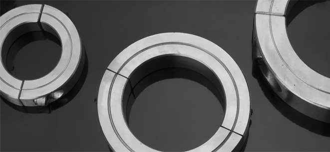
Rigid Coupling
A mechanical device used to connect two shafts to transmit rotary motion and torque. With a more compact design than flexible couplings, rigid couplings ensure efficient torque transfer by tightly connecting two shafts mainly through rigid connecting elements.
Characteristics
1. No backlash when carrying loads.
2. Rigid connecting elements provide a tight connection between the two shafts for efficient torque transmission.
3. Simple construction for easy installation and maintenance. 4. Lack of vibration damping and compensation making it unsuitable for high-speed environments.
Advantages
1. High efficiency: Due to the rigid connection, rigid couplings have no elastic deformation or sliding, and are able to transmit torque efficiently, making them suitable for applications that require high transmission efficiency.
2. High Accuracy: It provides higher axial alignment and motion accuracy for industrial applications that require precise motion transfer, such as servo systems.
3. Simple construction: Rigid couplings are relatively simple in construction allowing for easy manufacture, installation and maintenance.
4. Cost effective: Rigid couplings are generally cheaper than other types of couplings.
Disadvantages
1. High alignment requirements: Less tolerant of deviations between shafts and more demanding in some cases. It is necessary to ensure that the height of the two connected shafts is aligned during installation, otherwise it may lead to premature wear, increased vibration or even damage to the equipment.
2. Inability to absorb vibration and shock: Inability to absorb shock and vibration from starting, stopping or running the motor, especially if the shaft system is subjected to shock loading, which can cause damage to the equipment.
3. Not suitable for high speed: Due to the lack of vibration damping and compensation, it is not suitable for high speed rotating environments as this can lead to excessive vibration and thermal expansion problems.
4. Unable to handle varying shaft speeds: If there is a large difference in shaft speeds, a rigid coupling may not be able to effectively absorb and adjust for this difference, which can easily lead to vibration and noise.
Applications
1. Precision machinery and equipment: Precision machinery and equipment requiring high precision and high efficiency transmission, such as CNC machine tools, laser cutting machines, etc.
2. Motor drive systems: Commonly used to connect motors and loads to ensure efficient torque transmission.
3. Engine and transmission system: In the engine and transmission system of automobile, ship and other transportation vehicles, rigid coupling can be used to connect the engine and transmission.
4. Turbomachinery: Rigid couplings are also widely used in turbomachinery, wind turbines and other equipment.
Summary: Suitable for low speed, high precision, high alignment requirements, but not suitable for complex working conditions that require buffering, vibration damping or compensation function.
Flexible Coupling
Allow for a certain degree of axial, radial or angular misalignment and are capable of absorbing vibration and shock. These couplings utilize a flexible material or construction to provide more flexibility in accommodating misalignments and changes in motion between shafts.
Characteristics
1. Employs flexible connecting elements, such as springs, rubber or sheet metal, to provide greater deformation capacity. It is able to tolerate some misalignment of shafts and is suitable for applications where alignment accuracy is not required.
2. By using flexible elements, flexible couplings can absorb and minimize shocks and vibrations transmitted to the equipment.
3. Different materials and structural designs can be used to suit different working environments and application requirements.
4. Compared with rigid couplings, flexible couplings usually produce less noise during operation.
Advantages
1. Vibration damping: Shocks and vibrations transmitted to the equipment can be absorbed and reduced through the use of flexible elements. It helps to protect adjacent equipment and shafts and reduces mechanical damage.
2. Flexibility: The presence of flexible elements allows the flexible coupling to tolerate a certain degree of axial, radial or angular deviation with a large deformation capacity. It is able to adapt to a number of motion changes in the work, improving flexibility in practical applications.
3. Reduced bearing burden: By absorbing vibration and shock, the flexible coupling can reduce the burden on neighboring bearings, protect the connected equipment from damage, and extend bearing life.
4. Noise reduction: Compared with rigid couplings, flexible couplings usually produce less noise during operation.
Disadvantages
1. Low transmission efficiency: Compared with rigid couplings, flexible couplings may have some energy loss in the torque transmission process, and the transmission efficiency is relatively low.
2. Lifetime limitation: Flexible elements such as rubber or metal springs may fail due to aging, fatigue or overload.
3. Unsuitable for high precision transfer: Due to the presence of flexible elements, flexible couplings may not be as good as rigid couplings in transferring motion with high precision.
4. Maintenance requirements: Flexible couplings can be more complex and require regular inspection and maintenance to ensure performance, which can also lead to increased operating costs.
Applications
1. Drive train: Used to connect equipment on different axes in a drive train to accommodate shaft misalignment and vibration.
2. Industrial machinery: Such as grinders, lathes, milling machines, etc. Flexible couplings are used between spindles and motors to provide proper alignment and vibration damping.
3. Pumps and compressors: Used to connect drive motors to rotating equipment to minimize vibration and improve smooth operation.
4. Vehicle drive systems: In the drive systems of automobiles, ships and other vehicles, flexible couplings can be used to mitigate the impact of engine torque on the drive system.
Summary: Flexible couplings have good application prospects in situations where vibration or shock needs to be absorbed, or where there is misalignment between shafts.
Gear Coupling
A system of gears is used to realize the mechanical connection between shafts. Gear couplings are categorized into gear teeth in mesh and gear teeth out of mesh.
Characteristics
1. Transmission of torque and rotary motion using a gear system. The gears on the two shafts are embedded, thus connecting the shafts.
2. Gear systems provide a high degree of motion accuracy, making gear couplings suitable for applications where precise transmission of rotary motion is required.
3. usually stable in operation, providing a relatively smooth transmission.
4. Through precise gear design, gear couplings can maintain a high level of efficiency when transmitting power.
Advantages
1. Overload protection: When subjected to excessive loads, gear couplings can protect equipment from damage by slipping or disengaging.
2. Accurate transfer of motion: Gear systems provide a high degree of motion accuracy, making gear couplings widely used where precise motion is required.
3. Durability: Gear couplings offer good durability and longevity due to the wear-resistant materials typically used in gear manufacturing.
4. Reliability: Gear couplings typically have a long service life due to their robust construction.
Disadvantages
1. Higher cost: Gear couplings can be more costly compared to rigid couplings.
2. Noise: gearing and gear meshing can be noisy, especially at high speeds and high loads.
3. Difficulty of installation: It is necessary to ensure proper alignment and adjustment between the two shafts, otherwise wear or vibration may result.
4. Lubrication requirements: Adequate lubrication is required for proper operation of the gears to minimize friction and wear. Maintaining and managing the lubrication system may require additional cost and labor.
Applications
1. Industrial drive systems: Gear couplings are widely used in industrial drive systems, such as mechanical equipment, production lines and production machinery.
2. Marine propulsion system: Connection between marine diesel engine and propeller.
3. Automotive transmission system: In the transmission system of automobiles and other means of transportation, gear couplings are used to connect the engine and the transmission system.
4. Wind turbines: In the drive train of wind turbines, gear couplings are used to transfer the rotary motion of the wind turbine to the generator.
Summary: Gear couplings are used in a wide range of industrial applications where high torque transmission and precise motion transfer are required.
Diaphragm Coupling
A flexible coupling, usually consisting of a plurality of thin plates (usually stainless steel). These sheets are able to deform elastically under torque, allowing a certain degree of axial, radial or angular misalignment.
Characteristics
1. The flexible lamellas are designed to absorb and dampen transmitted vibrations and shocks to a certain extent.
2. Usually tolerates a certain degree of axial, radial or angular misalignment, which increases its flexibility in practical applications.
3. Due to the lightweight design of the diaphragm, the rotational moment of inertia is small, making it suitable for high-speed applications.
4. Because of the thin sheet design, diaphragm couplings are usually free of expansion and contraction problems and are suitable for some high or low temperature environments.
Advantages
1. Lightweight design: Usually relatively lightweight, which helps to reduce the overall weight of the equipment.
2. Low inertia: Due to the lightweight design of the diaphragm, the moment of inertia is low, making it suitable for high-speed applications.
3. No lubrication required: Lubrication is usually not required, reducing maintenance costs.
4. Vibration damping: Through the elastic deformation of the diaphragm, shocks and vibrations transmitted to the equipment can be absorbed and reduced.
Disadvantages
1. Potential for bending: When subjected to high torque, the diaphragm may bend to a certain degree, which can affect the performance and life of the coupling.
2. Limited axial displacement capability: Despite their flexible design, diaphragm couplings have a relatively limited axial displacement capability and may not be suitable for applications requiring significant axial deflection.
3. Temperature sensitivity: In extreme temperature conditions, the elastic properties of the diaphragm may be affected and special consideration needs to be given to the temperature range.
4. Torque limitations: Diaphragm couplings may have some limitations on torque transmission compared to some other types of couplings, especially at extreme high torque or high speeds.
Applications
1. Engines and Transmissions: Can be used to connect engines and transmissions in vehicles such as automobiles, ships, etc.
2. Transmission systems: Used to connect equipment on different axes to accommodate shaft misalignment and vibration.
3. Medical equipment: Also used in medical equipment where low vibration and noise levels are required.
4. Industrial machinery: Commonly used in various types of industrial machinery, such as pumps, fans, compressors and so on.
Summary: A common and effective choice in applications where vibration, shock, or shaft misalignment needs to be absorbed, as well as applications that require low shaft weight.
Oldham Coupling
The connection between the shafts is realized based on the relative movement of the slider to the guideway. This design permits a certain degree of axial and angular relative movement of the shafts and can accommodate large radial and angular misalignments.
Characteristics
1. Using the relative sliding of the slider and the guideway to connect the shafts, which allows the shafts to perform a certain range of axial and angular movements.
2. Due to the rapid wear, the tool is usually suitable for low speed or low torque applications.
3. The sliding connection makes it flexible and capable of absorbing some degree of vibration and shock.
4. Because of the usual sliding connection between the slider and the guideway, they are not subject to expansion and contraction problems in some cases.
Advantages
1. Low inertia: Due to the lightweight design of the diaphragm, the moment of inertia is low, making it suitable for high-speed applications.
2. Vibration absorption: The sliding connection of the diaphragm absorbs a certain amount of vibration and shock, helping to protect adjacent equipment and shafts.
3. No lubrication required: Usually no lubrication is required, reducing maintenance costs.
4. Long service life: Couplings have a long service life due to the use of high-strength materials in their manufacture.
Disadvantages
1. Friction and wear: The operating principle of slide couplings involves sliding friction, which can lead to wear and tear of the slides and guide rails. Long periods of use and high load conditions may require more frequent maintenance and replacement.
2. Lower transmission efficiency: Due to the presence of friction, slider couplings may be less efficient than some other types of couplings and there may be some energy loss.
3. Precision manufacturing required: The manufacturing of slide couplings requires a certain degree of precision to ensure the fit and stability of motion between the slide and guideway, which may result in relatively high manufacturing costs.
4. Limited axial and angular displacement: Although slide couplings can provide some axial and angular displacement, their displacement capacity is relatively limited. They may not be suitable for applications where large axial offsets or angular movements are required.
Applications
1. Printing machinery: Commonly used in printing machinery and other equipment requiring relative shaft displacement.
2. Packaging machinery: In some packaging machinery that needs to adapt to different size packages, it may be used to connect the drive system. 3.
3. Textile machinery: There are also applications in some textile machinery, such as looms.
4. Elevators and lifts: Connection between the traction machine and the traction sheave to absorb vibration and ensure safe operation.
Summary: It should be noted that slide couplings are not suitable for all types of transmission needs, especially where high precision transfer of motion is required.
Chain Coupling
Connects two shafts with a chain, similar in design to a chain drive system, usually consisting of a sprocket, chain and two connecting shafts.
Characteristics
1. Adopts the principle of chain drive to connect two shafts through sprockets and chains. Due to the design characteristics of the chain, the chain coupling has a small external dimension.
2. Using wear-resistant chain material, it has better durability and life.
3. The design is relatively flexible and it can accommodate a certain degree of axial and angular misalignment.
4. The chain design can absorb vibration and shock to a certain extent, which helps to mitigate the transmitted impact force.
Advantages
1. Adaptability: The flexibility of chain makes the chain coupling have certain adaptability, which can tolerate axial and angular changes and compensate the relative displacement between the connected shafts, and it is suitable for the occasions that do not have high requirements on the center precision.
2. High torque transmission: Chain couplings are usually able to withstand relatively high torque and are suitable for some applications requiring high torque transmission.
3. Compact size: Due to the design characteristics of chain, the chain coupling has a small external dimension.
4. Easy maintenance: The maintenance of chain coupling is relatively simple, and the service life can be prolonged by checking the wear of the chain and lubricating it at the right time.
Disadvantages
1. Poor abrasion resistance: For applications with high loads or long running times, chains may wear faster, which may require periodic chain replacement, increasing maintenance costs.
2. Inefficient transmission: Chain couplings can be less efficient than some other types of couplings because of the frictional losses typically associated with chain transmissions.
3. Regular lubrication required: Chain couplings often require regular lubrication to ensure proper operation, otherwise the friction of the chain will cause wear and tear and reduced life.
4. Relatively heavy: Due to the design of the chain and sprockets, chain couplings are relatively heavy, which may not be suitable for some applications where lighter shaft weights are required.
Applications
1. Conveying machinery: Used to connect drive and transmission shafts to transmit torque and rotary motion.
2. Agricultural machinery: Can be used to connect different components, such as the transmission system of a tractor.
3. Lifting and transportation equipment: Power transmission of heavy equipment such as cranes, elevators, etc.
4. Mining machinery: Power transmission of ore crushers, conveyor belts and other equipment.
Summary: A simple, reliable and highly adaptable type of coupling, especially suitable for some applications requiring high torque transmission and high tolerance for axial and angular deviation.
Conclusion
Couplings are common components in mechanical transmission systems, which play a key role in various industrial and mechanical applications, helping to mediate misalignments, vibrations, and shocks between shafts while transmitting power.
Different types of couplings have their own benefits, and engineers should consider a combination of factors when selecting and designing a system based on specific application requirements to ensure that the system is reliable and efficient as well as capable of achieving optimum performance in a given application environment.
If you still have questions about couplings, feel free to consult with machining and manufacturing experts like CYCO.