It is a well-known fact that CNC machining produces parts of consistent quality and high precision, even for parts with complex shapes. So, do you want to know what measuring tools are used in CNC machining to measure the size, shape and other parameters of the part to ensure machining accuracy and quality.
Continue reading to explore about measuring tools with CYCO.
Measuring Tools
Measuring tools are a kind of equipment or tools that are used to measure, evaluate, or record physical quantities. These tools are used in various fields including manufacturing, construction, scientific research, medicine, and engineering. Measuring tools are used to obtain accurate values of physical quantities such as dimensions, volumes, masses, temperatures, pressures, velocities, currents, voltages, and so on.
Different measuring tools are suitable for different measuring tasks, and the specific measuring tools depend on the physical quantities to be measured and the accuracy requirements. In practice, CNC machining centers may be equipped with a number of different types of measuring tools to facilitate quality control at various stages of the production process.
Measuring tools commonly used in CNC machining include: vernier calipers, micrometers, height gauges, gages, snap gauges, coordinate measuring machines, laser scanners, edge micrometers, hardness testers, and projectors.
Next we will introduce some of the above tools in detail.
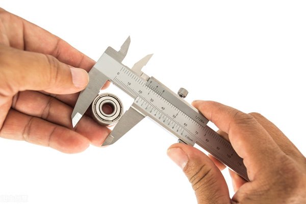
Vernier Caliper
Used to measure the length, diameter, depth and other dimensions of an object. It is a versatile tool that is widely used in manufacturing, machining, construction, laboratories and other fields. Vernier calipers have two movable legs for holding the object to be measured and reading the dimensions by dial or digital display.
Main Components
- Jaws: There are two jaws, one is fixed and the other is movable. The distance between these two jaws can be adjusted to accommodate objects of different sizes.
- Master Scale: There is usually a master scale for reading dimensions in whole numbered sections.
- Spiral Scale: On the moveable leg, there is a spiral scale for reading the dimensions of fractional parts. This can be a dial, a digital display or a numerical scale.
- Scale: The scale on a vernier caliper is usually measured in mm or inches. The density of the scale determines the resolution of the measurement.
Use Steps
- Open the jaws of the vernier caliper and clamp the object to be measured.
- After clamping the object, close the jaws to ensure a firm grip.
- Obtain the size of the integer part by reading the value on the main scale.
- Get the dimensions of the fractional part by reading the value on the spiral scale.
- Add the integer and fractional parts to get the total size of the object.
Suggestions and Precautions
- Keep Clean: Ensure that the measuring jaws of the vernier caliper and the surface of the object to be measured are clean and dust-free before measurement to avoid affecting the measurement results.
- Correct Clamping: Make sure that the jaws are clamped in the correct way when using the calipers to avoid tilting or shifting, which may affect the accuracy of the measurement.
- Gentle Operation: Avoid excessive force during operation to avoid damaging the precision parts of the vernier calipers. Especially when clamping the jaw, avoid clamping too tightly.
- Periodic Calibration: This ensures the accuracy of the measurement results. Depending on the frequency of use, calibration at regular intervals is usually necessary.
Micrometer
A highly accurate measuring tool used to measure very small dimensions. It is often used in industrial and scientific applications where extreme precision is required. The micrometer derives its name from its ability to provide a measurement resolution of one thousandth of a millimeter (0.001 mm) or one hundredth of a millimeter (0.01 mm).
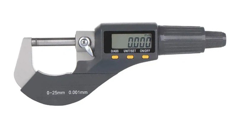
Main Components
- Master Scale: The main body, usually a straight ruler-like strip of metal. It has a master scale engraved on it and is used to read the whole number portion of the dimension.
- Helical Probe: The movable part, which can be pushed in or pulled back by rotation. The helical probe is usually threaded and is used to make contact with the object to be measured and to measure the dimensions of the object by means of a scale reading.
- Scale Ring: Located on the master scale and used to read the dimensions of the whole numbered parts. The scale ring is usually engraved with the main scale of the master.
- Spiral Scale: Located on the spiral probe and used to read fractional parts of a dimension. The scale on the spiral scale is usually denser and provides higher resolution.
- Scale Line: Some micrometers may have a scale line on the helical scale, called the spiral scale or Vernier scale, which is used to further improve the accuracy of the measurement.
Use Steps
- Open the micrometer and ensure that the helical probe is not overextended. If necessary, adjust the position of the helical probe by rotating it so that it makes gentle contact with the object being measured.
- Gently clamp the micrometer’s legs to the object being measured, ensuring a firm grip, but do not apply excessive force as this may affect the accuracy of the measurement.
- Read the scale on the master scale, which is usually the whole number portion of the dimension. Ensure that the reading is accurate by aligning the nearest scale.
- Read the scale on the spiral scale, which is usually the fractional part of the dimension. The scales on the spiral scale are more dense and require careful alignment to obtain an accurate reading.
- Combine the master scale and spiral scale readings to get the total size of the object being measured. Note the units, usually in mm or inches.
Suggestions and Precautions
- Gentle Operation: Use care and gentleness as excessive force or harsh operation may result in damage to the probe or measurement errors.
- Avoid Over-Rotation: Avoid over-rotating the helical probe. Use moderate force to rotate to prevent thread damage or failure of the micrometer’s mechanical components.
- No Excessive Oscillation: When using the micrometer, try to avoid excessive oscillation or rapid movement. Excessive movement may result in unstable or difficult to read accurately.
- Cleaning and Maintenance: Regular cleaning ensures that the screw probe, dials and other parts are free of dust, grease or other dirt. Keeping it clean will ensure the accuracy of the measurement.
Coordinate Measuring Machine
A high-precision measuring device used to measure the geometric size and shape of an object in three-dimensional space. Typically used in a wide range of manufacturing applications including machining, automotive industry, aerospace, and more. CMMs can measure complex parts and provide highly accurate and repeatable measurements.
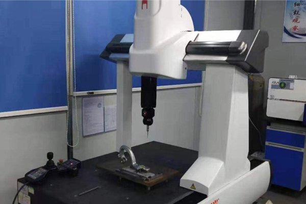
Main Components
- Measurement Sensors: They are usually equipped with different types of measurement sensors, including trigger probes, optical sensors and laser scanners. These sensors can be selected to measure in a suitable way depending on the geometrical characteristics of the object to be measured.
- Probe Heads and Joint Systems: The probe head is usually supported by a joint system, capable of moving in three axes. This design allows the probe to be positioned along the X, Y and Z axes for the purpose of measuring an object in all directions.
- Table: The object to be measured is usually placed on the table of the CMM. The table can be fixed or rotated to measure features in different directions.
- 3D Coordinate System: A 3D coordinate system is used to determine the location of measurement points. The coordinate system consists of three axes, X, Y and Z, which allow the probe to be accurately positioned at various points on the object being measured.
- Computer Control System: Motion and measurement are usually controlled by a computer that performs the measurement task through a predefined program. The computer is also used to analyze data and generate measurement reports.
Use Steps
- Fix the object to be measured on the table of the CMM.
- Set up the measurement program of the CMM according to the measurement task, including selecting the appropriate measurement sensor and measurement path.
- Position the probe at the starting point of the object to be measured using the joint system of the CMM.
- The CMM follows a predetermined path and uses the measurement sensor to measure the object under test. The probe records the coordinates of each measurement point.
- The computer analyzes the measurement data and generates a 3D model or measurement report.
- Based on the results of the analysis, a measurement report is generated that includes information about the object’s size, shape, and location.
Suggestions and Precautions
- Suitable Environment: Maintaining suitable environmental conditions is critical to the accuracy of the CMM. Environmental factors such as temperature, humidity and vibration may have an effect on measurement results, so it is important to maintain a relatively stable environment.
- Cleaning and Maintenance: Keep the CMM clean, including the probes, sensors, and workbench. Try to avoid accumulation of dust and dirt, which may affect measurement accuracy.
- Periodic Inspection: Regularly check all components of the CMM, including mechanical parts, electronic components and computer control system. Any abnormalities should be dealt with promptly.
- Prevent Vibration: Try to avoid introducing external vibration during the CMM measurement process. Vibration may interfere with the measurement results.
Laser Scanner
A device that uses laser technology to perform three-dimensional measurements and obtain surface geometry information. It can be used for a variety of applications, including industrial manufacturing, engineering design, reverse engineering, and cultural heritage preservation.
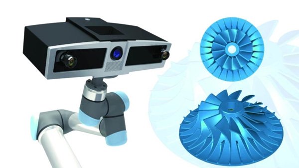
Main Components
- Laser Emitter: Emits a laser beam to scan the target surface.
- Receiver or Sensor: Receives signals reflected back from the laser beam for measuring distance and surface features.
- Lens: Used to focus the laser beam so that it can accurately illuminate the target surface.
- Rotating Stage or Moving Mechanism: Some laser scanners have a rotating or movable stage to allow scanning at multiple angles or positions to obtain more comprehensive data.
- Control Unit: Controls the operation of the laser scanner, including the emission of the laser light, the reception of data, and the movement of the platform.
- Data Processing Unit: Processes and analyzes the data collected from the laser scanner to generate a 3D model or point cloud.
Use Steps
- Check whether the components are in good working condition, then place the laser scanner in the area to be measured and make sure it is stable and safe.
- Select the appropriate scanning parameters according to the need, such as the power of the laser, scanning speed, resolution and so on.
- Set the size and position of the scanning area and determine the specific area to be measured.
- Calibrate the laser scanner before scanning. This includes calibrating the relationship between the laser transmitter and receiver to ensure accurate measurement results.
- The area to be measured is scanned appropriately and the position or angle of the scanner can be adjusted as required.
- Once data acquisition is complete, the point cloud data is stored or transferred to the data processing unit. The point cloud data is processed using specialized software to generate a 3D model, mesh or other surface representation.
- Perform quality control on the generated 3D model to ensure the accuracy and consistency of the measurement results.
Suggestions and Precautions
- Safe Operation: Use laser protective eyewear or other safety measures to avoid direct exposure of the laser beam to the eyes to prevent visual damage from the laser beam.
- Proper Cleaning: Clean the laser scanner’s lenses, laser transmitter and receiver regularly. Accumulation of dust or dirt may affect the accuracy of measurements.
- Prevent Overexposure: Avoid scanning overly bright or highly reflective surfaces without the laser scanner being properly adjusted to prevent overexposure and distortion.
- Regular Maintenance: Check all parts of the equipment, both mechanical and electronic, periodically to ensure proper operation.
Projector
Also known as an optical projector or profile projector, a precision measuring device used to inspect the size, shape and position of a workpiece. It achieves accurate measurement of a workpiece by projecting an image of the workpiece onto a screen and comparing it to a standard image of known dimensions.
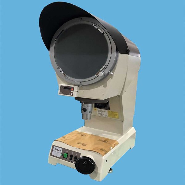
Main Components
- Light source: Usually adopts high brightness halogen lamps or other types of light sources to provide uniform illumination for the workpiece.
- Lens System: Composed of a set of lenses, it is responsible for magnifying and focusing the image of the workpiece on the screen.
- Table: Used to place the workpiece to be tested, which can be adjusted manually or electrically to change the position and angle of the workpiece on the screen.
- Screen: Used to display the image of the workpiece.
- Control Panel: Used to set and adjust the working parameters of the instrument, such as the brightness of the light source, the focal length of the lens and so on.
- Scale and Indicator: The scale is used to measure the dimensions of the image on the screen, and the indicator (e.g. crosshairs) is used to identify specific points or features in the image.
Use Steps
- Place the workpiece on the working table and adjust the position and angle.
- Turn on the light source and look at the image of the workpiece on the screen through the lens.
- Adjust the focal length of the lens and the intensity of the light source to ensure that the image is clear and bright.
- Measure dimensions and features of workpieces using rulers and indicators, and compare them with standard images or drawings.
- Record measurement results, and analyze and process data as necessary.
Suggestions and Precautions
- Proper Lighting: Ensure that the lighting conditions of the projection environment are moderate, avoiding too strong or too weak a light, so as not to affect the clarity of the projected image.
- Lens Cleaning: Periodically clean the projector lens to avoid accumulation of dust or dirt to maintain image quality.
- Timely Maintenance and Care: Regularly perform maintenance and care of the projector, such as replacing the lamp and cleaning the filter.
- Correct Distance and Angle: Follow the recommendations for projection distance and projection angle provided by the manufacturer to ensure that the projected image maintains normal proportions and shape on the screen.
Surface Roughness Meter
Surface roughness is the spacing or height of tiny peaks and valleys on the surface of a material, which has a significant impact on the properties of the workpiece such as wear resistance, fatigue strength, corrosion resistance, etc. A surface roughness meter is an instrument used to measure the surface roughness of a material, which provides information about surface texture, unevenness and particle distribution. These instruments are widely used in industry, manufacturing, material science and quality control.
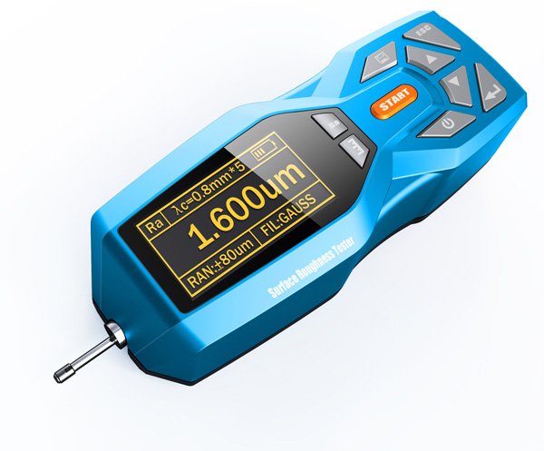
Main Components
- Sensor: Also known as a stylus, this is the key component for measuring surface roughness. It usually consists of a very fine and wear-resistant diamond tip that is used to make contact with the surface being measured.
- Actuator: Responsible for moving the sensor or workpiece so that the stylus can slide along the measured surface.
- Data Acquisition and Processing System: Converts the displacement changes generated by the stylus as it moves across the measured surface into an electrical signal, which is further converted into a surface roughness parameter value.
- Display Unit: Displays the measurement results in digital or graphical form.
- Control Panel: Provides the operation interface where the user can set the measurement parameters, select the measurement mode, etc.
- Working Table: Used to place the workpiece to be measured, and can be fine-tuned in X and Y directions.
- Fixing Device: Used to fix the workpiece to be measured to ensure that the workpiece will not move during the measurement process.
Use Steps
- Make sure the workpiece to be measured is stable and immobile, and use jigs or fixtures if necessary.
- Select the appropriate surface roughness parameter for measurement according to the material and application of the workpiece to be measured.
- Install the stylus on the sensor, make sure it is perpendicular to the measured surface and adjust the pressure of the stylus.
- Place the sensor in contact with the measured surface and move it along the preset measurement path. Take care to maintain a steady contact pressure during the measurement.
- The instrument automatically converts the displacement change generated by the stylus moving on the measured surface into an electrical signal, which is further converted into a surface roughness parameter value.
Suggestions and Precautions
- Choose Suitable Measuring Parameters: According to the material and usage of the measured workpiece, choose the appropriate surface roughness parameters for measurement.
- Install the Stylus Correctly: Ensure that the stylus is firmly installed and perpendicular to the measured surface.
- Clean the Measuring Area: Clean the measured surface of dust, oil and other impurities before measurement.
- Maintain Stable Pressure: Apply stable measurement pressure to avoid inaccurate measurement results due to too much or too little pressure.
- Calibrate the Instrument: Regularly calibrate the surface roughness gauge to ensure the accuracy of the measurement results.
Hardness Tester
Used to determine the ability of a material to resist external stresses and localized deformation. Hardness testing can help evaluate the strength, wear resistance and other important properties of a material. Different hardness testing methods and standards correspond to different types of hardness testers, commonly known as Brinell, Rockwell, Vickers and Richter hardness testers.
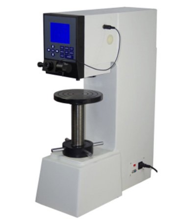
Main Components
- Loading System: Responsible for applying a certain pressure or impact force to the material being measured. This system can be manually operated or electrically or hydraulically driven.
- Indenter: The part used to press or impact into the surface of the material under test. Different hardness test methods use different shapes and sizes of indenter, such as Brinell hardness tester uses steel balls, Rockwell hardness tester uses conical or spherical indenter, while Vickers hardness tester uses diamond positive quadrangular cone.
- Indicator Device: Used to display the hardness value of the components, can be a mechanical pointer, electronic display or other forms of reading device.
- Fixture: A device used to hold the material under test and ensure that it does not move during the test.
- Control System: For automated hardness testers, there will be a control system to regulate and control the magnitude and holding time of the test force.
- Measuring System: Used to observe the indentation or to measure the size of the indentation. Depending on the hardness test method, the measuring system can be an optical magnifying glass, a microscope, or a sensor.
Use Procedure
- Make sure that the surfaces of both the hardness tester and the sample to be measured are clean and free of grease, impurities or dirt.
- Calibrate the hardness tester and adjust the support and positioning system of the hardness tester as necessary to ensure that the sample under test is in the correct position.
- Determine the appropriate test force and loading time. This step is not required for dynamic hardness testers such as the Richter hardness tester.
- Mount the specimen on the fixture of the hardness tester, making sure it is stable and aligned with the indenter.
- Start the hardness test and the hardness tester will apply a predetermined load to the surface of the sample under test.
- After the hardness test is completed, the hardness tester measures and records the characteristics of the surface impression, such as notch diameter for Rockwell or indentation diameter for Brinell.
- Clean the probe or indenter of the hardness tester promptly after the test is completed to prevent residues from affecting the next test.
Suggestions and Precautions
- Environmental Conditions: Keep the temperature and humidity of the test environment within the range allowed by the hardness tester specifications. Extreme temperatures and humidity may affect test results.
- Sample Surface Preparation: Before performing the hardness test, ensure that the surface of the sample under test is flat, clean and free of any depressions or protrusions. Where possible, carry out surface leveling.
- Correct Hardness Test Method: Select the appropriate hardness test method and load, adjusted to the hardness range of the material under test. The use of different hardness test methods may require different procedures.
- Maintain Constant Test Conditions: Keep loads, test times, and other test conditions constant during a hardness test. Varying test conditions may result in unstable test results.
- Avoid Repeated Testing of the Same Area: When performing multiple hardness tests, try to avoid repeated testing of the same area to prevent surface damage from affecting subsequent tests.
- Avoid Edge Effects: Try to stay away from the edge of the sample under test to avoid the influence of edge effects on the hardness test results. Usually test at a certain distance from the edge of the position.
Summary
Measuring tools play a vital role in manufacturing and engineering to ensure that products meet specifications, improve productivity, and ensure accuracy in quality control. This article describes a range of common measuring tools, including micrometers, vernier calipers, CMMs, laser scanners and surface roughness meters.
As a whole, these measuring tools play a key role in different stages of the production process, from quality inspection of raw materials to verification of the final product. Using these tools appropriately and following the correct operating procedures and precautions is essential to ensure product quality and improve manufacturing efficiency.
We, CYCO, specialists with over twenty years of CNC machining and manufacturing experience, have various measuring tools and professional staff. We can select the appropriate measurement methods and tools according to the needs of your products to ensure that the products we produce are of high quality and precision. We also offer all types of customization services to provide you with personalization while meeting the quality and accuracy of your parts.
Contact us now to start a new project!